For the 1996 model year, Honda changed the ST1100 from a 28-ampere alternator with a separate regulator/rectifier to a 40-amp one with an internal regulator. Having completed the installation of a 40 amp. alternator to my '91 ST, plus one on a '95 model, here are some tips that may help others who attempt the job.
First of all, credit must go to Alan Barbic for taking the challenge to attempt the first such conversion. His write-up is on Dale Wilson's ST1100 Archive of Wisdom web site at http://www.st-riders.com/st1100/. (That site has been taken down, though, but a copy of it resides on the Wayback Machine here.) Look under "Modifications" for "40-Amp Alternator Retrofit". There you'll find the list of parts that Alan used to make this worthwhile upgrade to his ST. Also, Jonathan Lewis (inventor of the "Lewis Pin" - see following), Jeff Bertrand, Jeff Jones and Alan Hunt shared their hints to simplify the installation further from what Alan did. Note that these later efforts reduced the number of parts that are needed. Use John O's list of parts (see below) instead of Alan's. What follows is not a complete step-by-step procedure but rather a list of issues that came up during the installation.
| I have done only two alternator installations. John Oosterhuis has done several, and has offered some meaningful addendums to my original write-up. I have inserted them in red type. |
Click here for John's list of tools, parts, supplies, etc. (everything but the beer!)
Click here for Mark Frost's write-up of the swingarm R&R. You will need this info, too.
Click here for Mark Hosier's write-up of the whole alternator change-out, including references to Haynes and Honda service manuals and to the tips below..
A Testamonial |
Hold it!How do I know whether I need to replace my alternator?Read this. |
1. When removing the three socket head bolts that retain the 28 amp. alternator, you may notice that they make a creaking noise while being loosened. That's because corrosion forms in their threads, since they don't screw into blind holes. Note: you will use one of these 6mm screws to make the Lewis Pin. On the second upgrade I worked on, I had to use an impact driver (one of those devices that you hit with a hammer) with a wobble extension and the appropriate size Allen wrench tip to get one of these bolts free. If that hadn't worked, it would have been necessary to drill the head off the bolt. That would require an extra-long drill bit. Don't fret about destroying the bolts, as they and the parts they screw into won't be used for the 40 amp installation.
John O. sez, "Borrow one of the genuine Lewis Pins Jon has made and distributed around the country for loan to ST1100 alternator upgraders. It'll work much better than any hand-made version of yours."
2. You will re-use the following parts from the alternator drive mechanism: nut, flat washer, forward ball bearing, shaft collar, cone washer, driven gear, damper spring, spring seat, flywheel (those last four parts stayed together for me), and the rear bearing retainer with its three attachment bolts. Here's a picture showing these parts from a late model ST1100 service manual with appropriate notes added (Thanks, John O.).
3. Before you remove the alternator drive gear nut, notice the ball bearing. Mine has a thin metal cover that hides the balls from view on one side only. Notice that the cover is facing the nut, rather than the gear. Also note the direction that the shaft collar and the cone washer face as you remove these parts.
4. The Haynes manual says to use wooden blocks in a vise to hold the alternator drive gear while loosening the nut. I found it easier to use my old car oil filter wrench, which has a metal band and a long handle, for the task.
5. Chill the new alternator drive shaft in the freezer for a couple of hours (Shrinkage!) before installing.
6. Use a piece of pipe to support the inner race of the new drive bearing while you tap the new shaft (oil it first) into the new bearing. The shaft is 20 mm diameter, so the pipe should be about 13/16" (20.6 mm) inside diameter and at least 3 1/2 inches (90 mm) long. (Black iron 3/4" pipe nipples 4" long at Home Depot cost about a dollar. The inside diameter on various samples I checked varied from 3/4" to 13/16". Make sure you get one that's 13/16", because you don't want it to be a tight fit on the shaft. If you take your new shaft to the hardware store, you can check the fit.) I put a few drops of motor oil into this bearing to pre-lube it.
John O. sez, "A piece of 1" OD schedule 40 PVC pipe works fine."
7. Use Loctite® on the threads of the three screws that fasten the bearing retainer.
8. Also use Loctite® on the alternator shaft nut.
9. Grease the O-rings to ease their installation.
10. The alternator drive gears are two pieces with a spring mechanism inside. This serves to eliminate all gear backlash, presumably to reduce gear noise, but possibly for some other benefit which I don't understand. To install the drive into the engine, these two gears must first be forced into alignment, and a 6 mm bolt slipped into an unthreaded hole to hold this alignment. The shop manual says to remove the exhaust system and oil pan so you can retrieve this bolt. But the Lewis Pin makes this removal unnecessary! The Lewis Pin is made by cutting off the head of one of the 6 mm bolts that held the old alternator together. This provides a smooth shank which will serve as the gear alignment holder. Cut off some of the threaded end so the pin is only about 9/16" (14 mm) long. Cross-drill near the threaded tip for fastening a wire for pulling the pin out through the oil drain plug hole.
John O. sez, "Again - use one of the available genuine Lewis Pins."
Cut a length of wire about 2 feet (600 mm) long. I used some soft steel wire about 1/16" (1.5 mm) diameter. Others have used coat hanger wire or stranded steel picture hanger wire. Drain the engine oil. Poke the wire into the drain hole and you will be able to insert it until it comes out the alternator installation hole. (Another approach is to use a length of 1/4" (6 mm) diameter polyethylene tubing, forming a conduit to feed the wire through from the top.) Mark a spot on the rear face of the alternator drive shaft in line with the 6 mm alignment hole. Insert the pin in the hole, using a screwdriver to force the gear teeth into alignment. It's best to try to get the minimum insertion to hold the gears in alignment, because that will ease the retrieval of the pin. Use some grease on the pin, too. Also put a glob of grease on the portion of the gear teeth where they will mesh with the drive gear in the engine. This will be in about the 1:30 o'clock location with the shaft oriented as described in the next paragraph.
John O. sez, "Use a 50% mixture of 3% moly grease and motor oil as per the Honda Service Manual."
Place the drive assembly in position and connect the wire securely to the Lewis Pin. (You don't want to lose this pin inside your engine.) You may want to wrap tape around the connection to make it less likely to catch on something inside the engine (particularly the edge of the oil drain plug hole). Position the mark you made on the shaft at the 4:30 o'clock angle, and insert the drive into the engine case while gently pulling the wire out the drain in order to keep the wire from bowing up into somewhere where it might get caught. I found it quite difficult to get the drive lined up, but was finally able to get the mechanism inserted by hand. It lacked being fully seated by about 1/8 inch (3 mm). Avoid any temptation to try to hammer the part into this position.
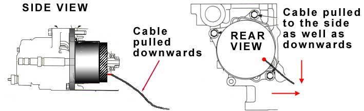
Here's a nice illustration prepared by Alan Hunt to show the use of the Lewis pin. You can see that the pin needs to be at the 4:30 o'clock position to minimize the angle that the cable pulls.
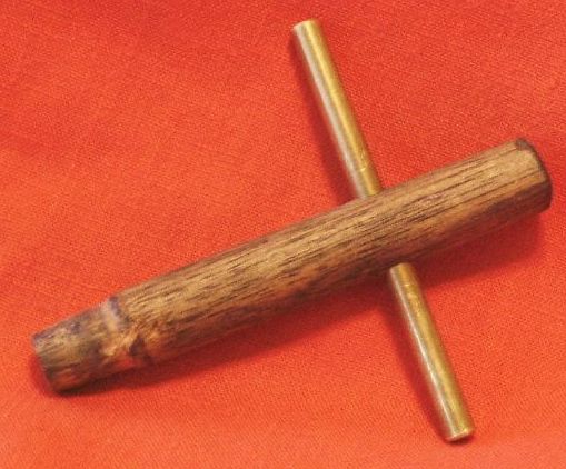
Here's a tip from Jim Frens: "The trick was to use a wooden dowel, whittled down so it could be inserted into the female end of the shaft which allowed me to turn the alternator shaft back and forth while pushing it into the engine. The combination of pushing and turning helped the two gears to mesh." Here's a photo of the "FrenSTick", with a cross-bar added by John O.
Then pull on the wire to disengage the Lewis pin from the gears. Make sure the pin comes out of the oil drain and isn't lost inside your engine.
John O. sez, "Again, use a genuine Lewis-Pin (machined/hardened/polished steel), clamp a vise-grips on the end and jerk sharply; should work the very first time. Jon designed a very fancy 3rd generation pin but with the proven reliability of the 2nd gen pin decided it wasn't worth producing."
I made sure the bolt holes lined up with those in the engine case. Then I used a hammer handle like a ramrod to seat the drive assembly the rest of the way. The lugs will seat against the engine case, though you'll still be able to see a machined area where the O-ring was installed as in this picture.
11. In most cases, the new alternator does not have to be taken apart to fit it into location. Just remove the sheet metal cover and set it aside for rework. Remove two bolts on the rear of the transmission. These bolts are one over the other, about at the centerline of the frame cross member, and have 10 mm hexagonal heads. (They are two of the seven that hold the gearshift linkage cover to the transmission, shown in this picture.) Also remove the bolt that holds the guide for the three drain tubes and the neutral sensor wire (12 mm hex). Remove the two bolts that hold the rear brake line to the cross member (10 mm hex). Bend the left hand bracket on the rectangular cross member upward about 30 degrees. After installation, be sure to bend this bracket back to its original shape. You don't want a hole in the bottom of your fuel tank.
John O. sez, "Note: California and 92-95 ABS models have a wire bail (holds/routes the tube(s) to the charcoal canister) on the lower frame cross-member which must be removed, and its weld bead must be ground flush in order to get enough clearance to get the alternator between the frame cross-members. Use zip-ties to secure the hoses later."
Now the alternator may be fed into location, passing it below the rectangular cross member. This is like one of those Chinese puzzles, where the parts don't seem like they can possibly fit together, but with careful, persistent trying, can be joined. I found two ways to do this.
John O. sez, "You shouldn't have to go to #3 below! The first two methods have worked for everyone I've assisted. Read them carefully, have patience and keep trying... it'll slip through *without* forcing it."
A third way to do it, from David Wallace, "Two cents on what worked for me for getting the alternator past the transmission and frame. I found that, if I disconnected the ground wire connected to the engine block and pulled it back out of the routing brackets, and disconnected the starter motor wire at the 30 amp fuse and pulled it forward, the alternator slipped in directly without any difficult twists or turns. It took me less time to disconnect, move, and reconnect the wires than I had spent on trying to get the right angle to slip the alternator in."
If all else fails and you haven't been able to get it in position within 15 minutes or so, split the alternator in two, as described at the old Archive of Wisdom mentioned in the second paragraph of this page, or in more detail at Craig Severson's write-up. Then reassemble the two pieces inside the frame. I was able to avoid splitting the alternator on my '91, but not on the '95.
12. Install the new 8mm mounting bolts. It is obvious that the torque in the Honda Service Manual, 42 lb. ft. /58 Nm, is much too high and is an editing error. This is supported by two facts:
- The manual calls the mounting bolts "Alternator shaft bolt"
- The torque spec for the much larger (14mm thread) "Alternator shaft nut" is 42 lb. ft./58 Nm.
The Honda manual shows that a standard 8mm flange bolt should be torqued to 20 lb. ft./27Nm. Use this figure.
13. Trim the cover per this picture and install. I tried to install mine without cutting it, but it just wouldn't fit past the frame members. After it was installed, the cut seems too big. Maybe you can get by with less trimming. I have tried (unsuccessfully) leaving a strip of metal around the edge of the opening I cut, rather than have the cut go all the way to the lip of the part. I'm sure you can get by with no cut at all if you're willing to pull the engine! =8^0
Per David Wallace, "I had removed the alternator cover before I installed the alternator and trimmed the cover similar to what you did. The alternator went in so easily after pulling the wires back that I believe it may be possible to install the alternator without removing the cover. I wasn't about to remove the alternator to see, but from eyeballing the clearance, it looked possible."
14. Re-install the upper hose guide. I added four inch (100 mm) extensions to each of the drain hoses, routed them around the right rear of the new alternator and into the wire lower guide. There's another guide slightly higher than this one, but it is too close to the alternator to use.
John O. sez, "I just installed complete, new (longer) replacement hoses."
15. I found a MAXI fuse block made by Littelfuse at Pep Boys. This uses a fuse the same type as the ones on the ST, but physically much larger, and the biggest rating Pep Boys had was 50 amps. I installed it where the old regulator/rectifier mounted. The new wiring harness reached that location, and I made up a short 10 gauge cable to go from there to the battery positive post. The cleanest installation uses the OEM fuse block. With either method, you may have to shorten the bolts mounting the fuse block so that they don't contact the fuel tank.
16. To delete the old regulator/rectifier connector, and generally clean up the wiring, unwrap the tape covering the wire harness far enough to expose all the yellow wires from the old red 3P connector to the R/R connector. Snip the white wire that goes to the 2P connector, leaving the black wire. Snip the red/white wire and the black wire going to the R/R connector and tape up their ends, because these circuits will be live. Here's a picture of what you are removing. Then re-wrap the black and the red/white ends along with the green ground wire, which you fasten using one of the mounting bolts for the new fuse block.
17. Chuck Chiodini came up with this one, "I test fired the engine/alternator before I bolted the swingarm/drive shaft back on, with no apparent ill effects. Yes, the output shaft did turn slightly in neutral, although it could be stopped by hand easily (don't try this at home kids! Professional driver, closed course disclaimer). No funny noises or any pieces/parts flying out during this smoke test. Was easy to see everything and check for oil leaks with all that swingarm hardware out of the way. Yes..I trust my work (heck..I even pack my own parachutes) but...why not check for any leaks and stuff while you are right there and can correct any problems without having to remove everything you just put back on?
I have modified Mark Hosier's reassembly sequence accordingly. The bike will run for a short time using the fuel in the float bowls. If you have a voltmeter connected to the battery when you start it, you will quickly see 14 volts or so after the bike starts. If you want to run it longer to check for oil leaks temporarily re-install the fuel tank.
Don't forget to re-install the transmission bolts. Enjoy your new amps!
PICTURES! Adam Koczarski took some pictures while he was doing the alternator installation on his ST. You may see them at this page on his web site. I think you will find the photos helpful.
MORE PICTURES! I found another web page on the alternator upgrade on Gunnar Reed's bike with lots of pictures. The Lewis pin wasn't used in this instance. At request of that site's webmaster, I have put some of the most useful of these photos here because he removed the ST1100 page from his site to free up some space..
EVEN MORE PICTURES! John Oosterhuis took some great photos of Rob Parker's installation. Thanks John and Rob.
MORE Rob Parker shot photos of the OEM fuse block installed on his bike.
AND FINALLY! Bill Royal submitted pictures using a sealed fuse block from Littelfuse. He came up with a clever mounting point for his added auxilliary fuse block, too. Pictures here:Photo 1 - Photo 2 - Photo 3
[ Top of Page ]
Last updated on January 30, 2014 © 2001-2014 M. E. Martin, all rights reserved.