Skene IQ-275A Intelligent Lighting Controller
The Skene IQ-275A allows for 3 brightness settings on low beam and 100% brightness on high beam. This model also has an “alert” mode which rapidly flashes at 100% powered when the high beam switch is double tapped.
The unit is programmed via the high beam switch. Triple tapping the high beam switch while the unit is starting up puts it into programming mode allowing you to select what percentage of brightness you want at each of the three low beam settings.
To change the brightness level follow these steps.
-
Ensure that the high beam switch is off, then turn on the ignition. The high beam will come on low power for 3 seconds and then flash briefly twice
-
To enter programming mode, as soon as you see the 2 rapid flashes, activate the high beam switch 3 times before 10 seconds elapse. The controller will respond by flashing the lamps back 3 times, signaling the controller is now in programming mode.
-
Once in programming mode, each time the high beam is turned on then off, the high beam brightness will increase by 10% until it reaches 100%. The next increment beyond 100% will cycle it back to 0% or off.
-
Exit the programming mode by turning the ignition off. The controller will also exit programming mode if there is no activity on the high beam switch for 20 seconds. The programmed brightness level is automatically saved and will apply the next time the ignition is turned on.
Because of the way the 2016 FJR LED lights are wired there is a slight issue using this controller with this bike. The Skene controller assumes you will be tapping one of its leads into a wire which is 0v on low beam and +12v on high beam. Because the 2016 FJR uses a high beam switch on the ground side of the circuit the switch wire will be +12v on low beam and 0v on high beam. This means you’ll need a “change-over” circuit to invert this behavior.
Here are wiring diagram showing what the high beam circuit looks like on low and high beam.
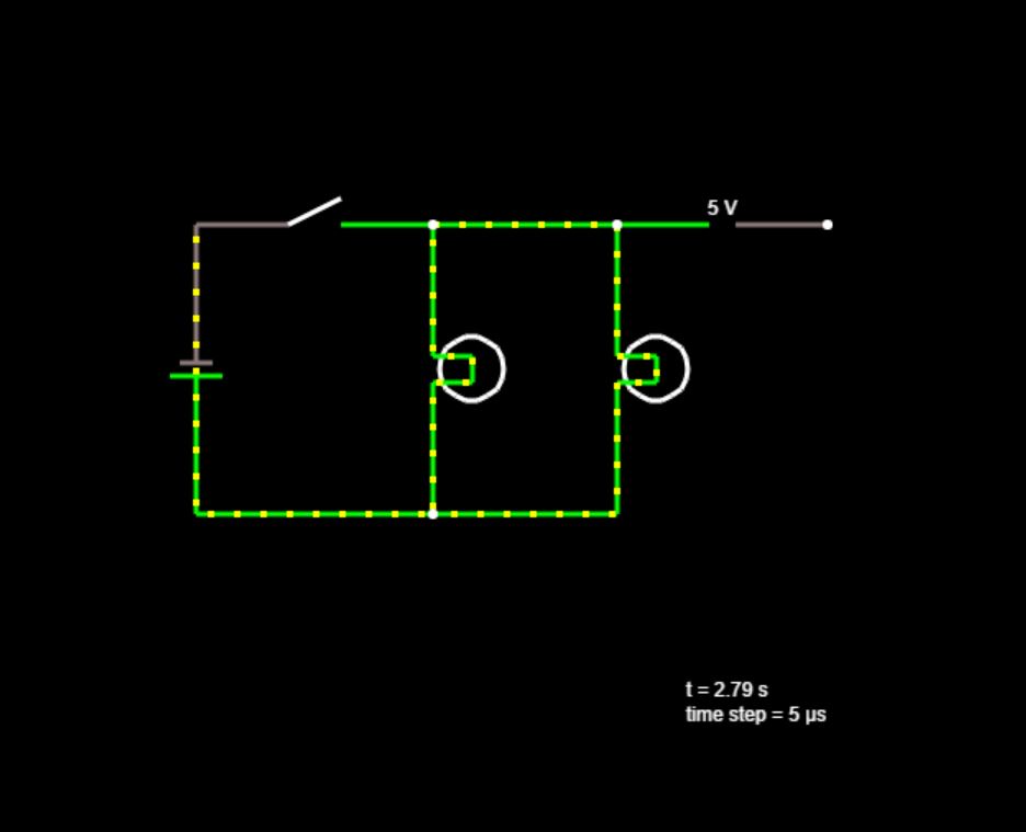 With the high beam switch open. Note +v on the volt meter.
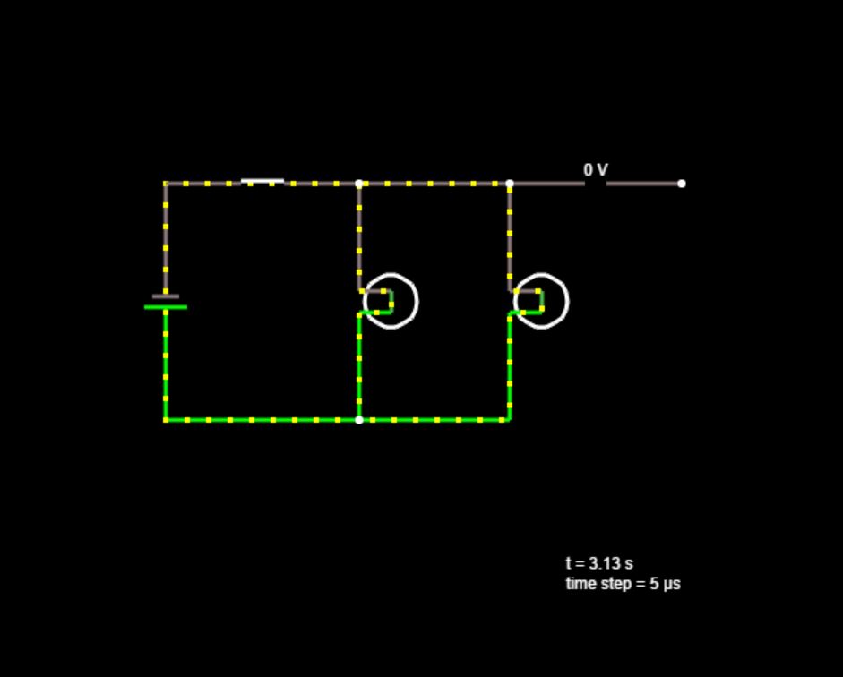 With the high beam switch closed. Note 0v on the volt meter.
I tried using a Bosch “change-over” relay which did work, but the load of the relay caused the high beam indicator to light at about 30% intensity on low beam.
With the help of a few EE friends we were able to come up with the change-over circuit shown below. This accomplishes the same function as the Bosch relay, but creates no load on the high beam circuit. The high beam indicator works as designed.
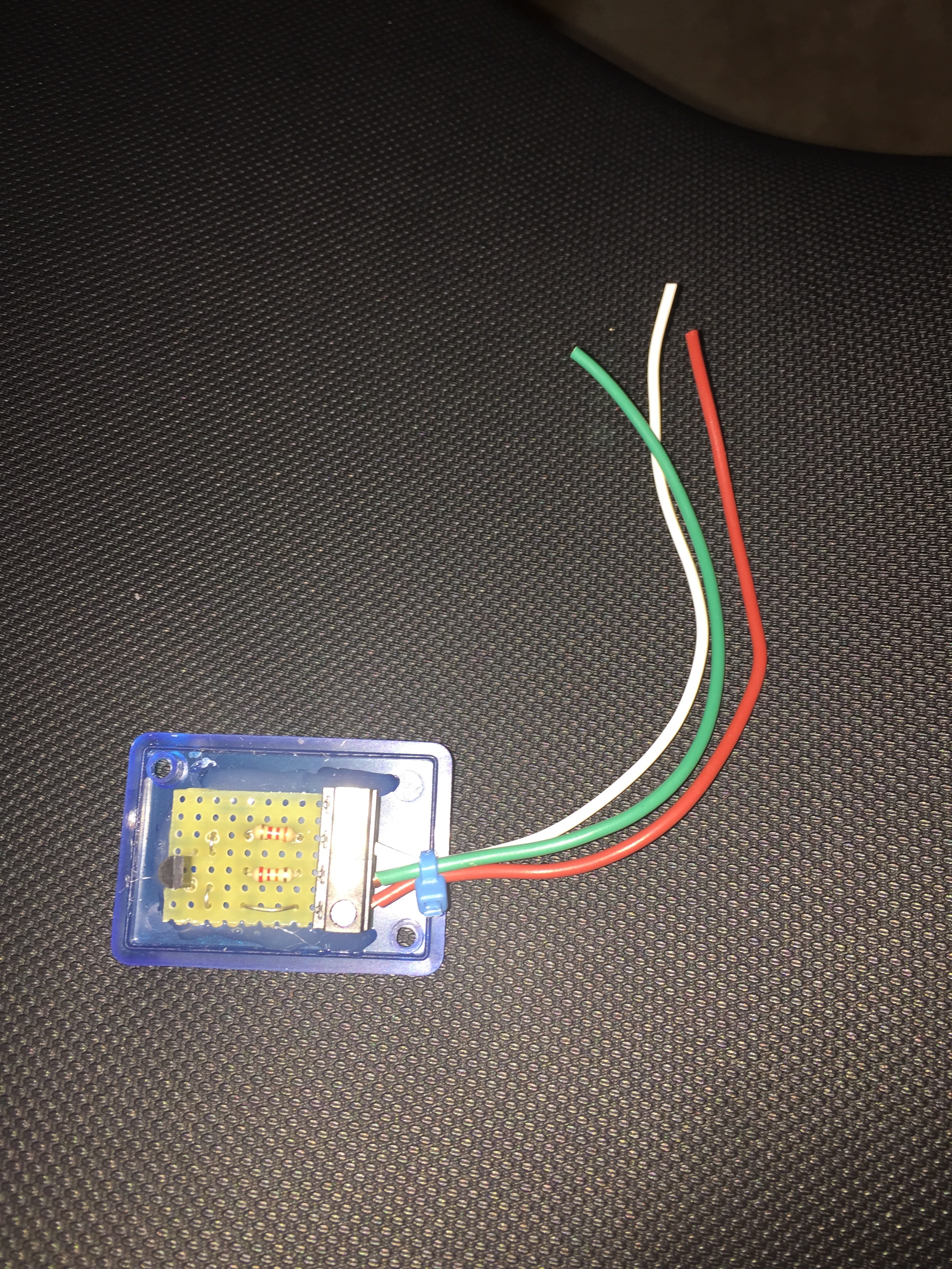
This change-over circuit connects to +12v, to the high beam circuit of the 2016 FJR and to the high beam (white) input wire on the Skene controller. When the FJR is on low beam and producing +12v on the high beam circuit the input on the Skene will see a “floating” signal from the change-over circuit. When the high beam switch is turned on the voltage on the high beam circuit goes to 0v and the change-over circuit sends +12v to the Skene controller.
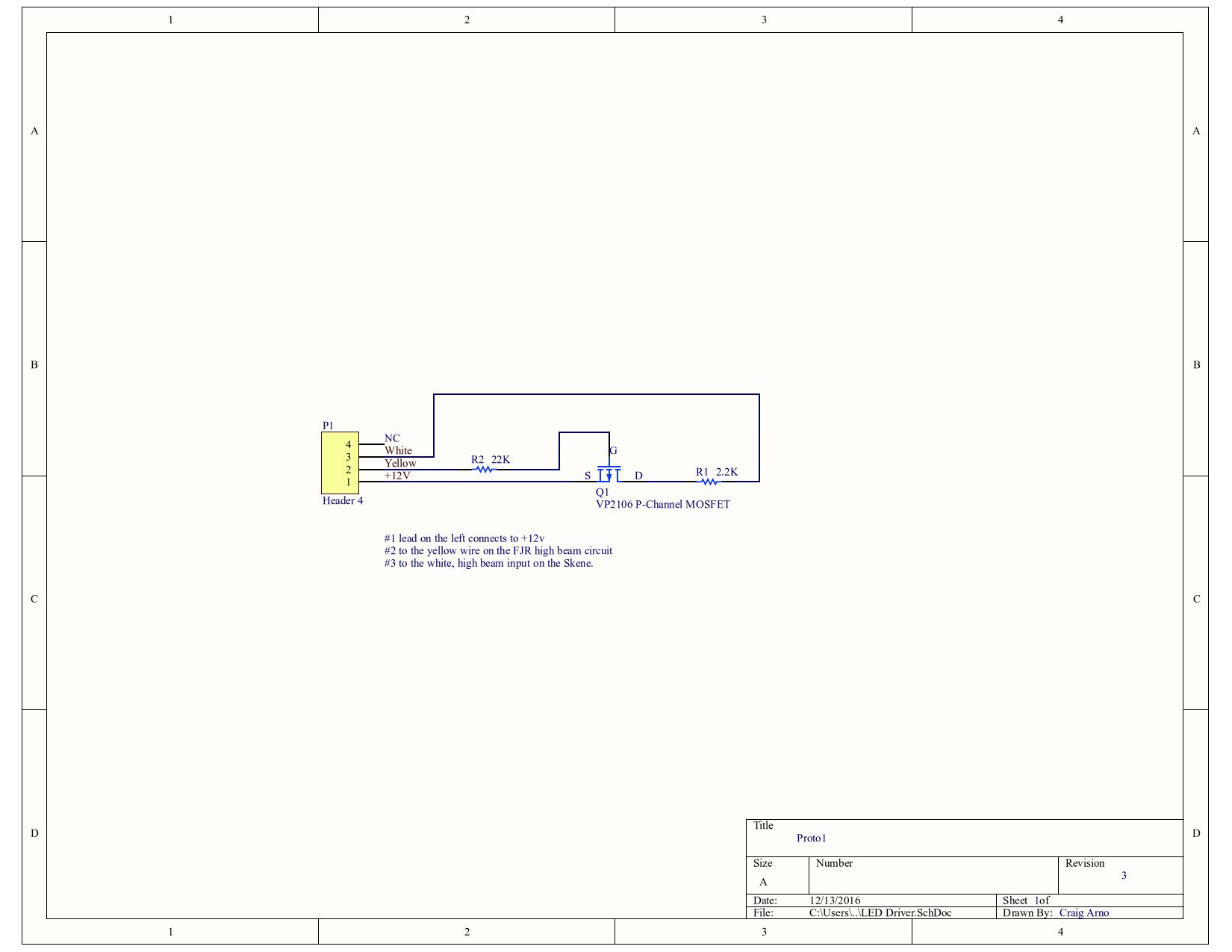
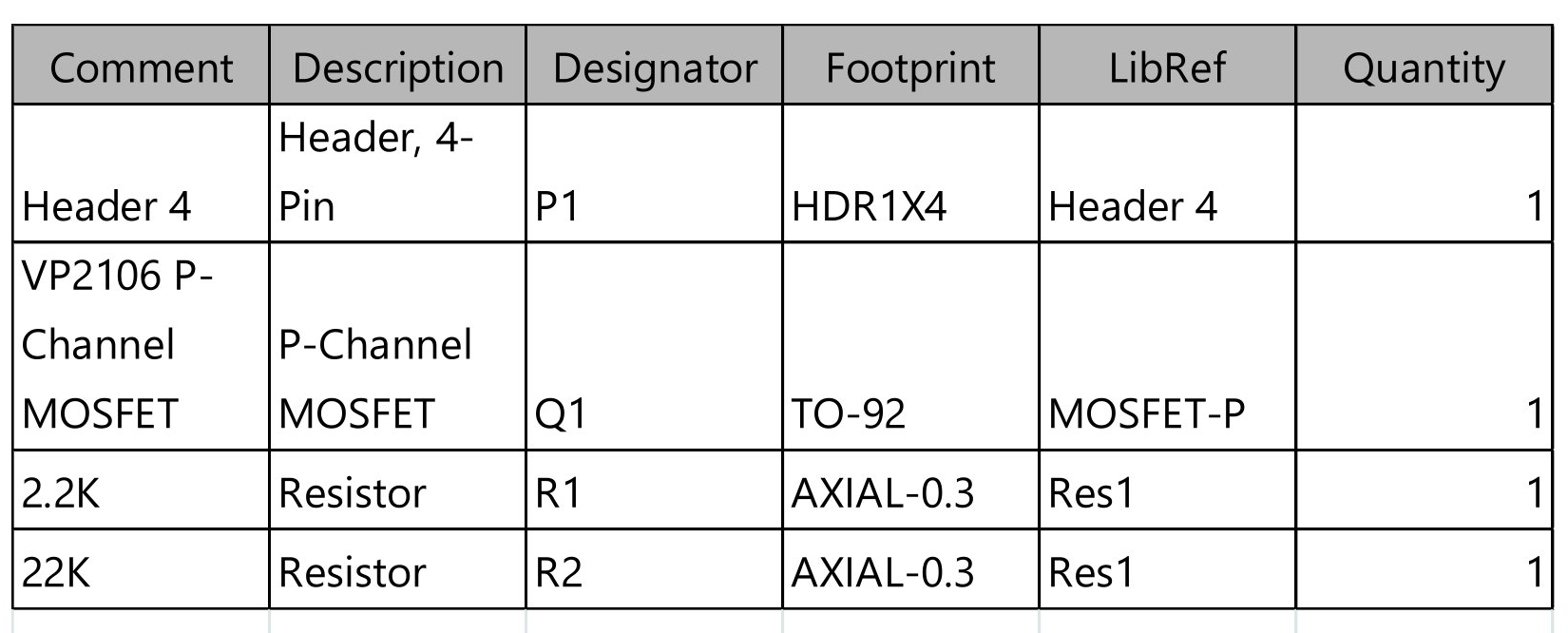
You can use the link below to download the PDF shown above which includes “clickable” parts and a BOM (Bill Of Materials). The clickable link is most useful for the FET as it includes URL’s to the Data Sheet and the Vendor – Digikey.
Thanks Craig Arno!
LED Driver schematic with clickable links

Link to spec sheet here
The part can be ordered here
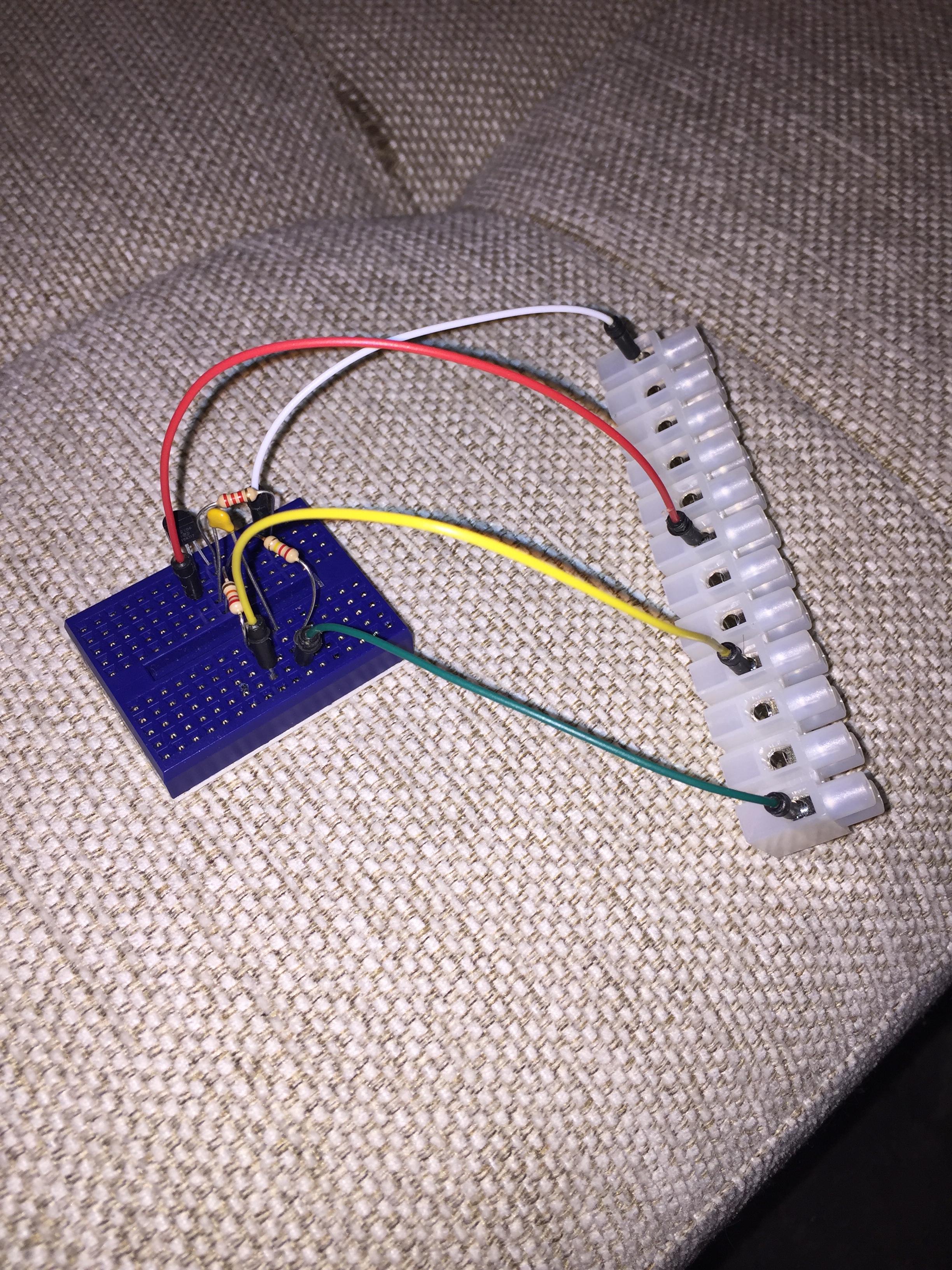 This is the test circuit. More parts than required. The final circuit with fewer parts is shown in the diagrams and pictures below.
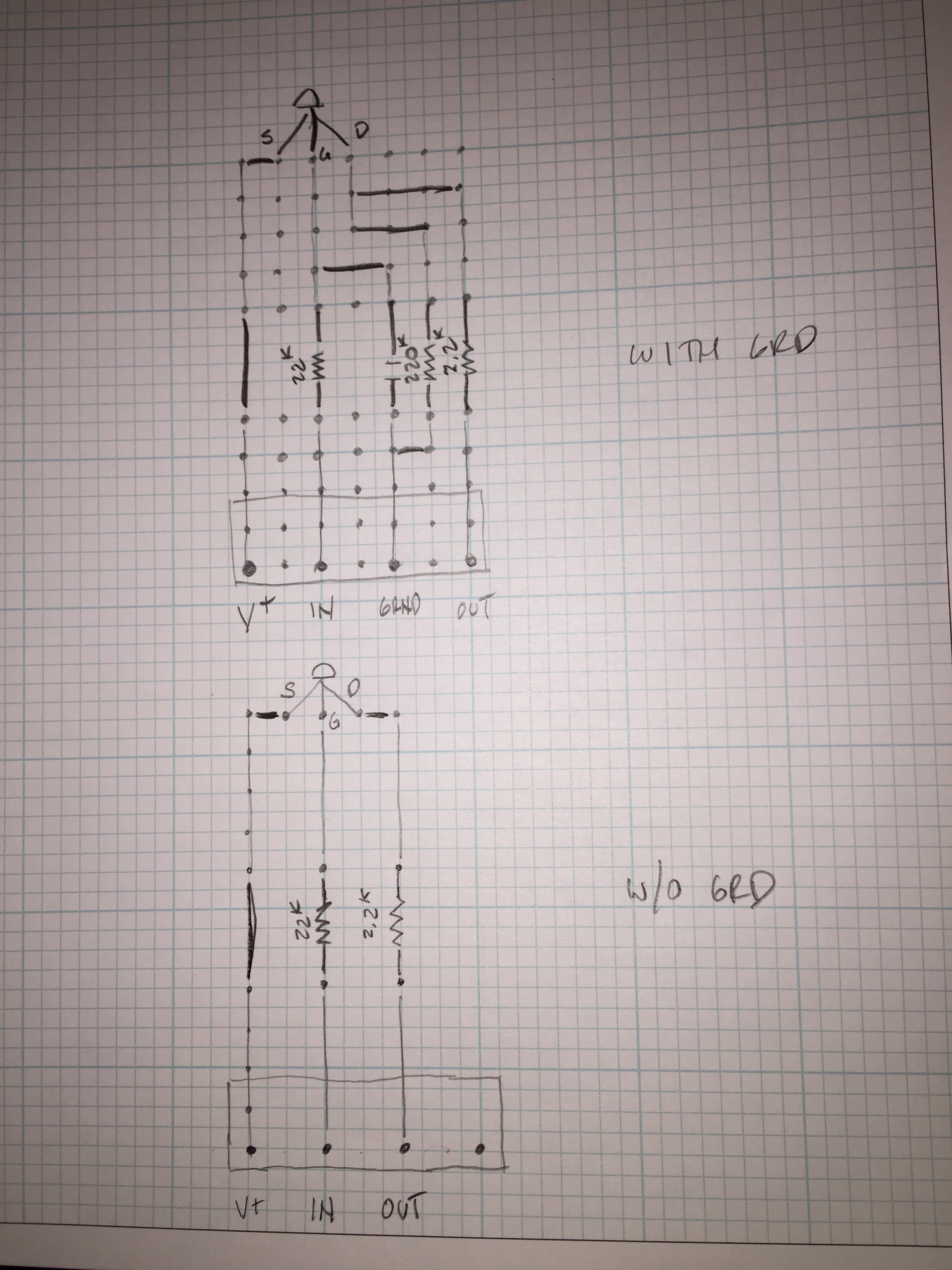 In the end, after testing, it was determined the simple version on the bottom of this sheet was adequate.
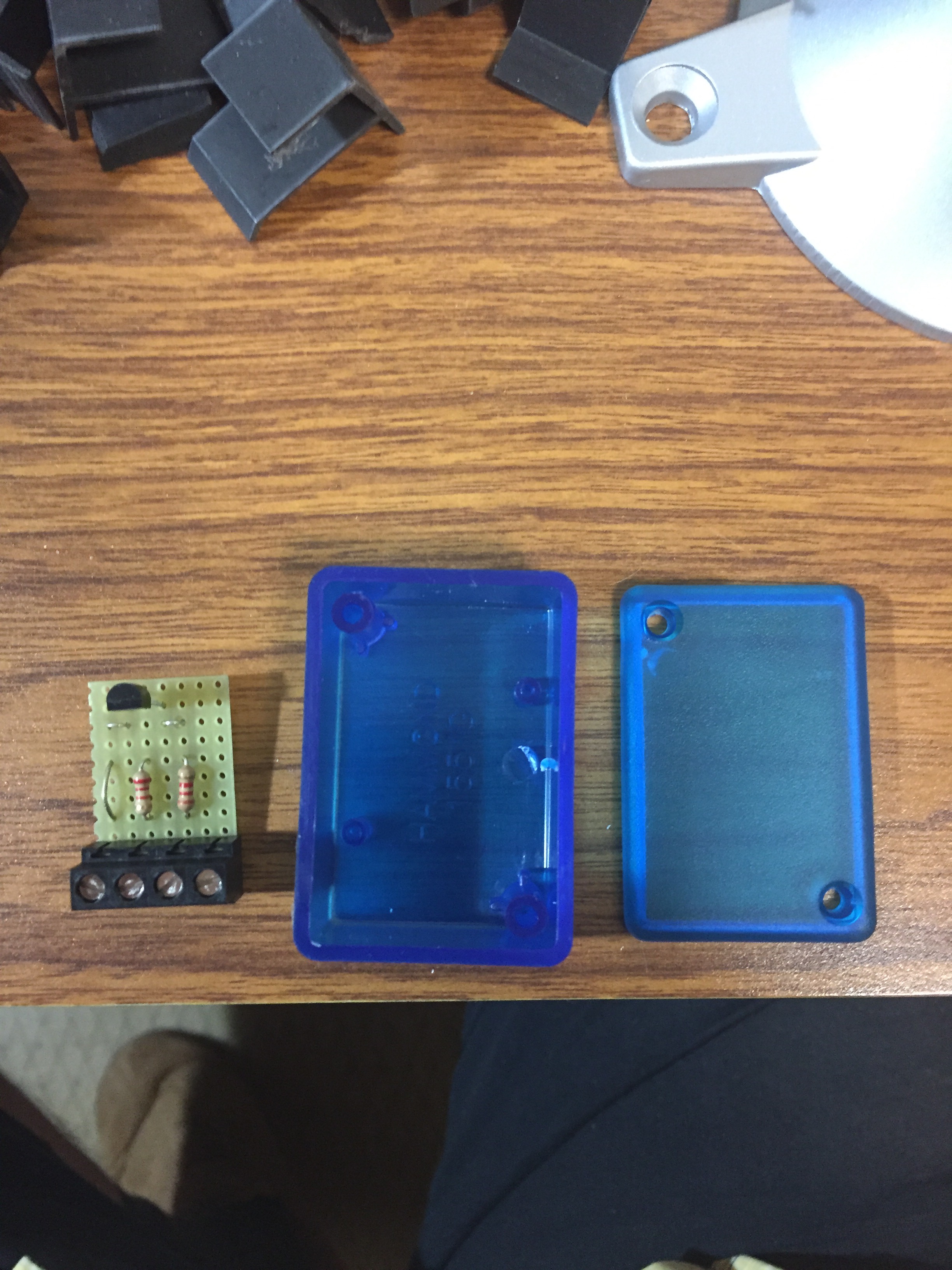 Here is the assemble board. I found a small box at Vetco which was a perfect fit for the board. The #1 lead on the left connects to +12v, #2 to the yellow wire on teh FJR high beam circuit, #3 to the white, high beam input on the Skene.
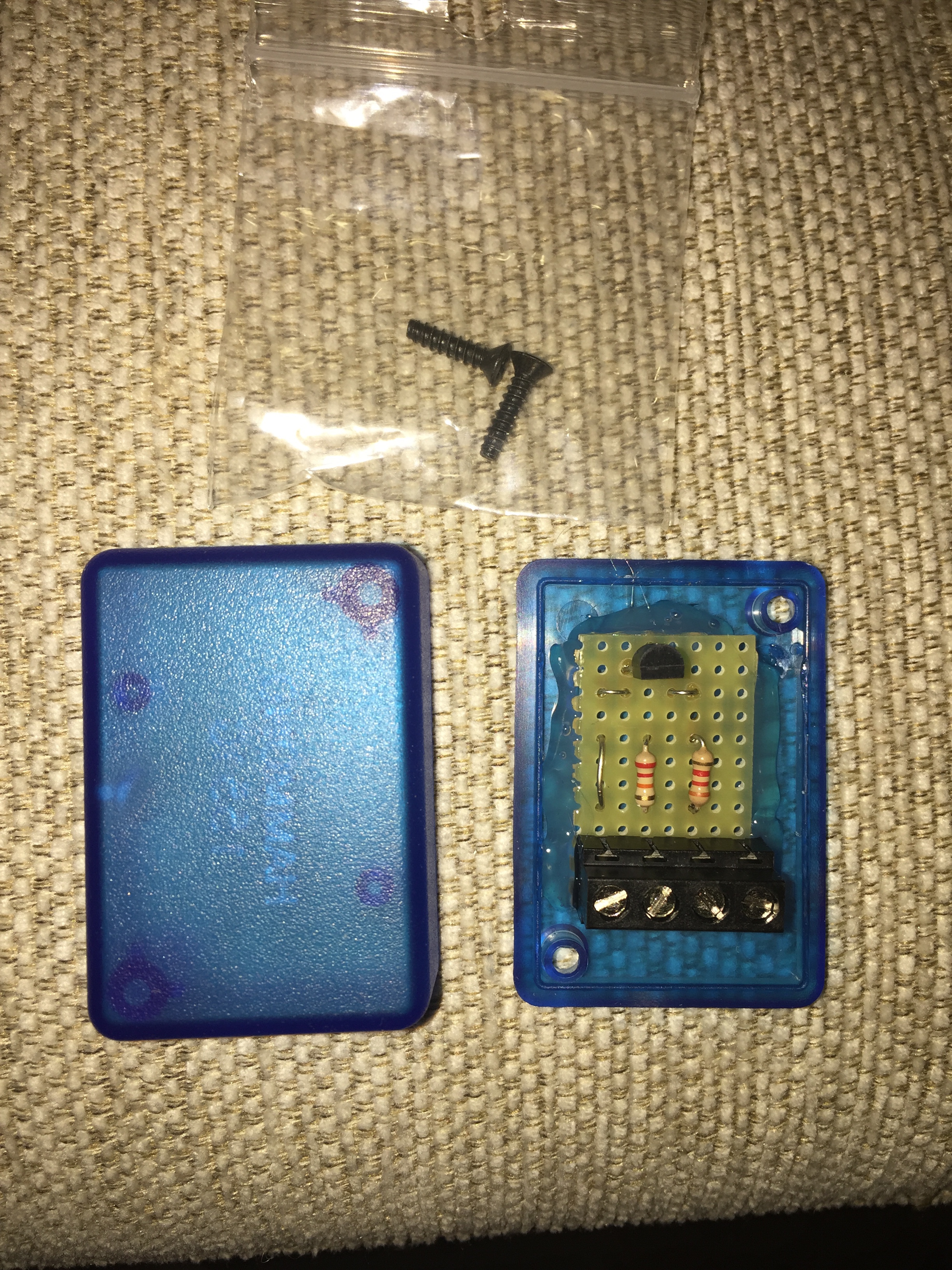 Circuit board hot glue to the lid of the box.
Video demonstrating the high-low beam and the “alert” mode.
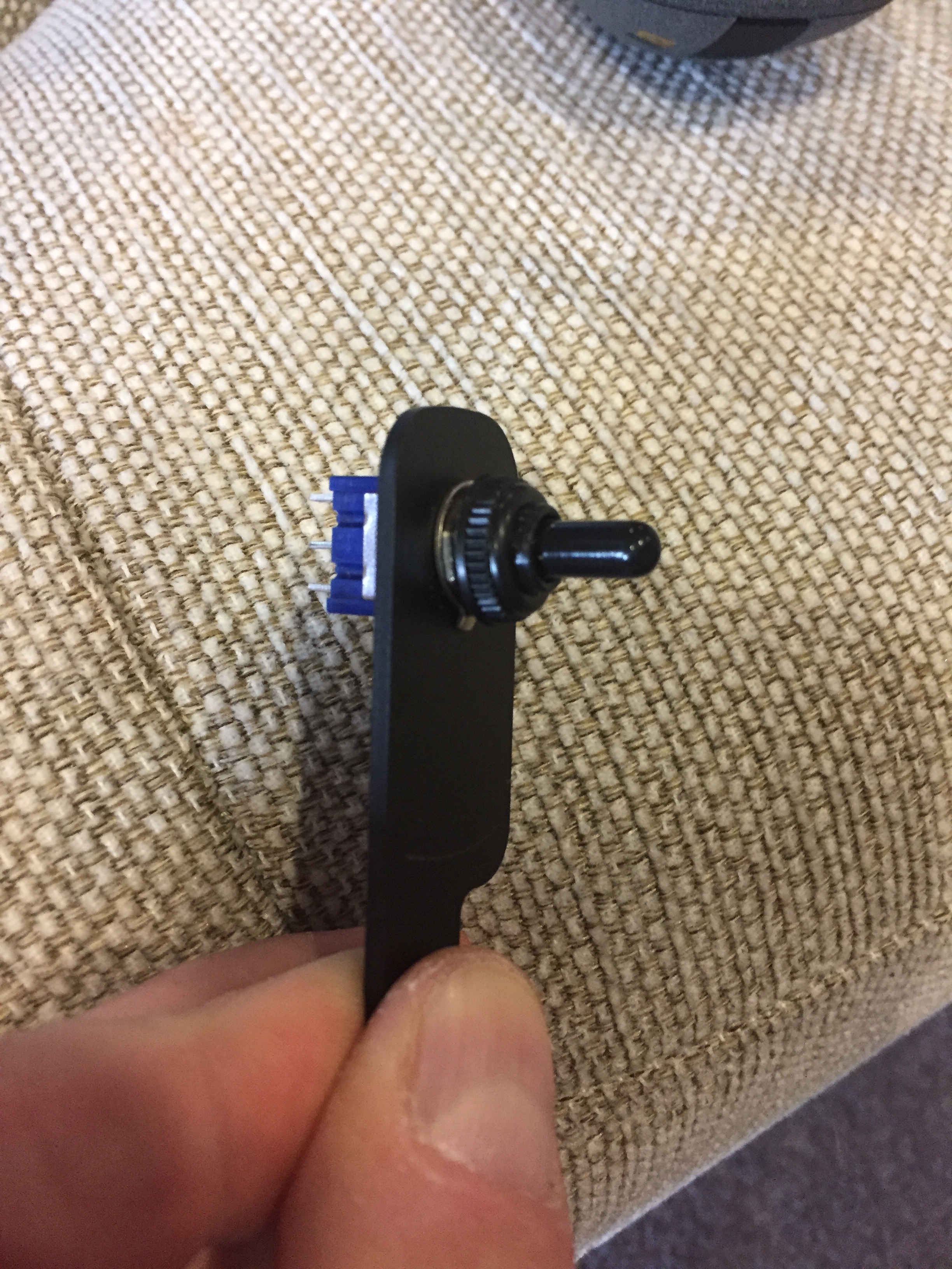 Clutch reservoir mounted triple throw switch for the 3 low beam brightness settings.
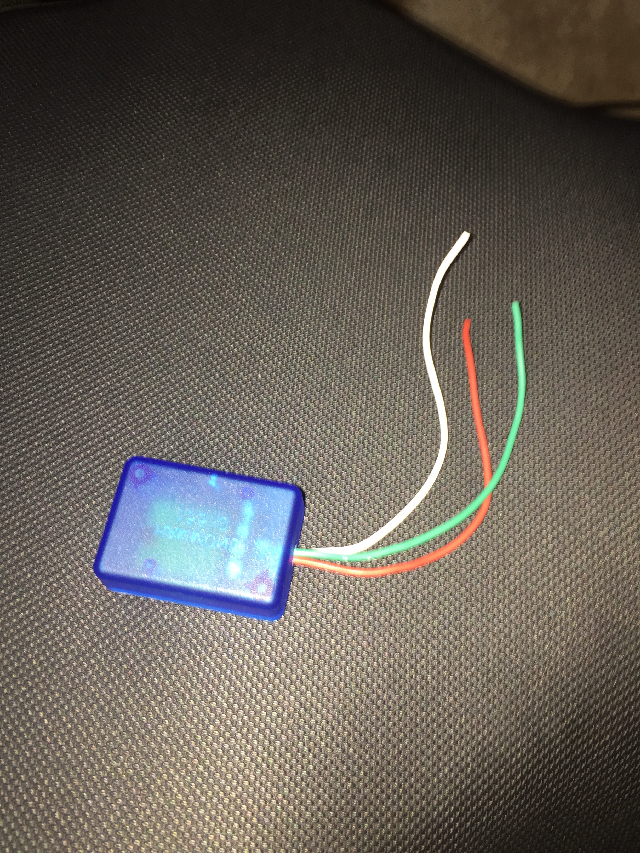
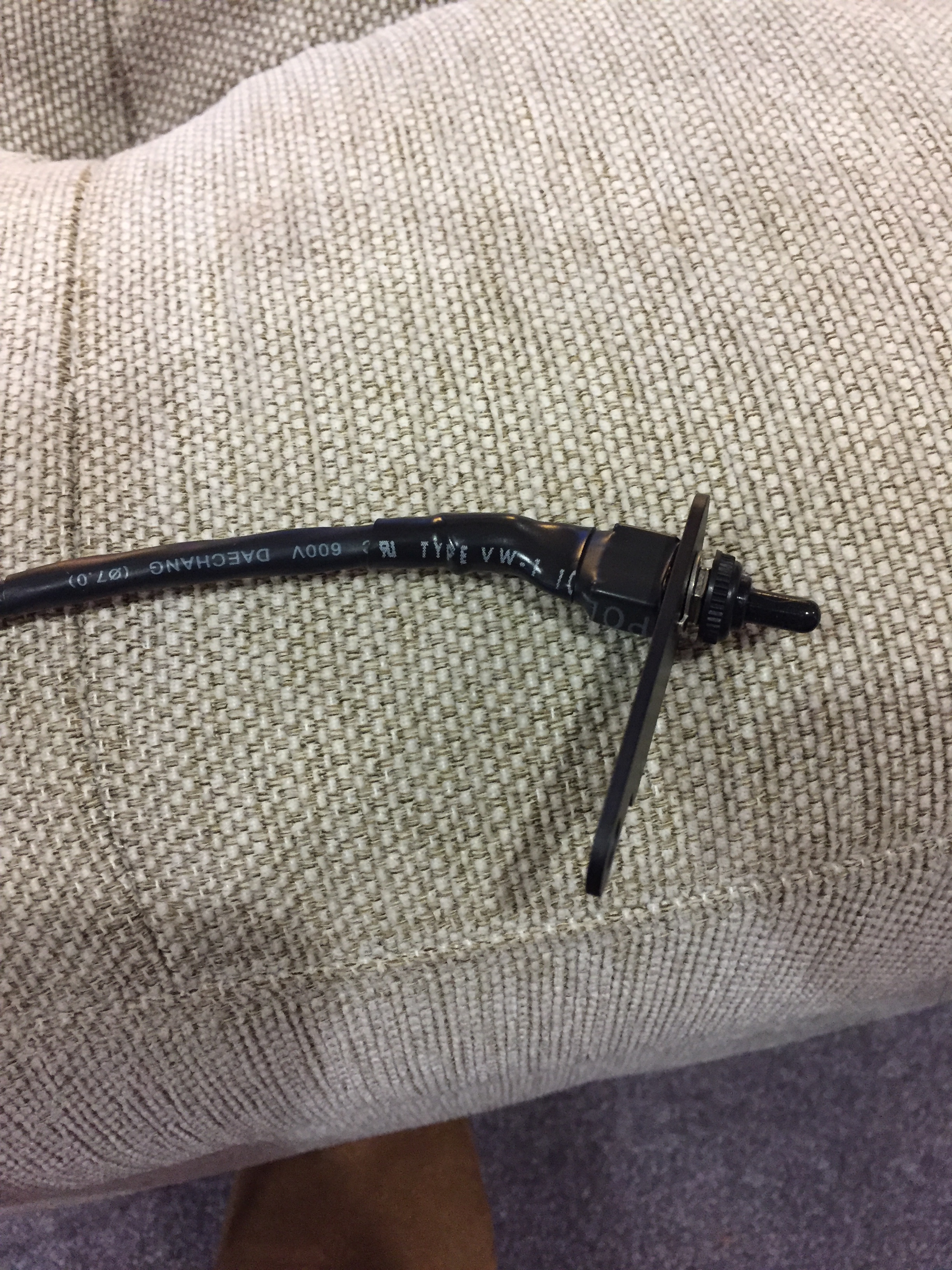 Used 4 different sizes of heat-shrink to cover up the solder connections and bare wire.
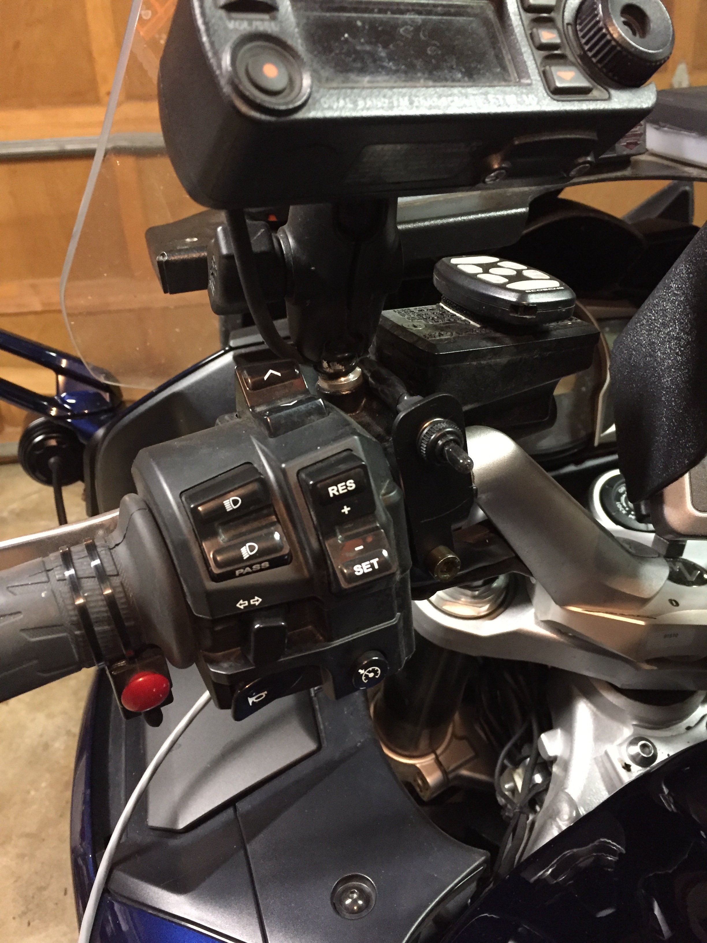 Switch mounted in place via the lower clutch reservoir mounting bolt. I configured the three settings to 0% (off), 20% & 60%. The 20% settings is for night and is about as bright as the stock headlights. The 60% settings is for daytime running. I get 100% on high beam.
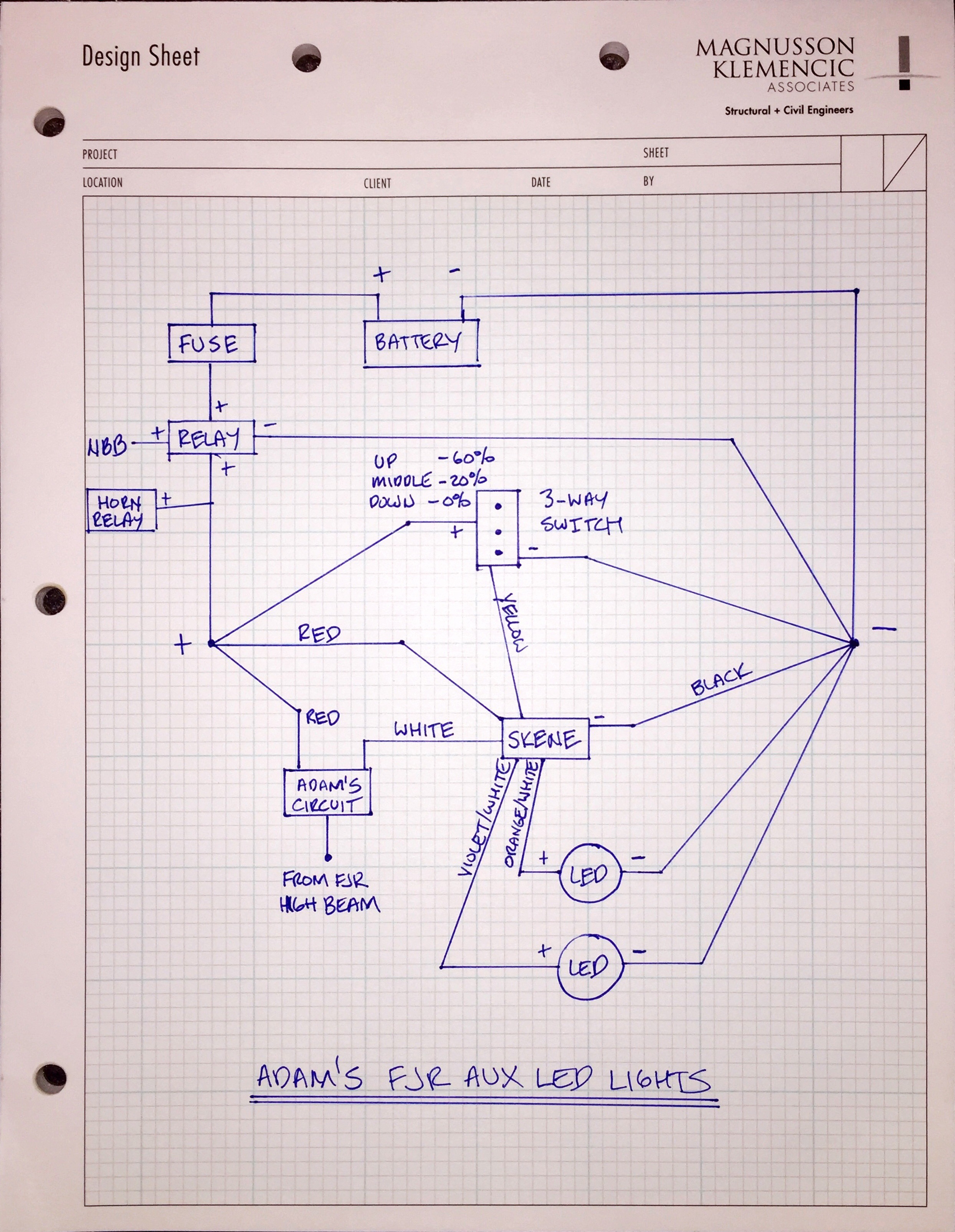 Schematic with entire auxiliary lighting system and controllers.
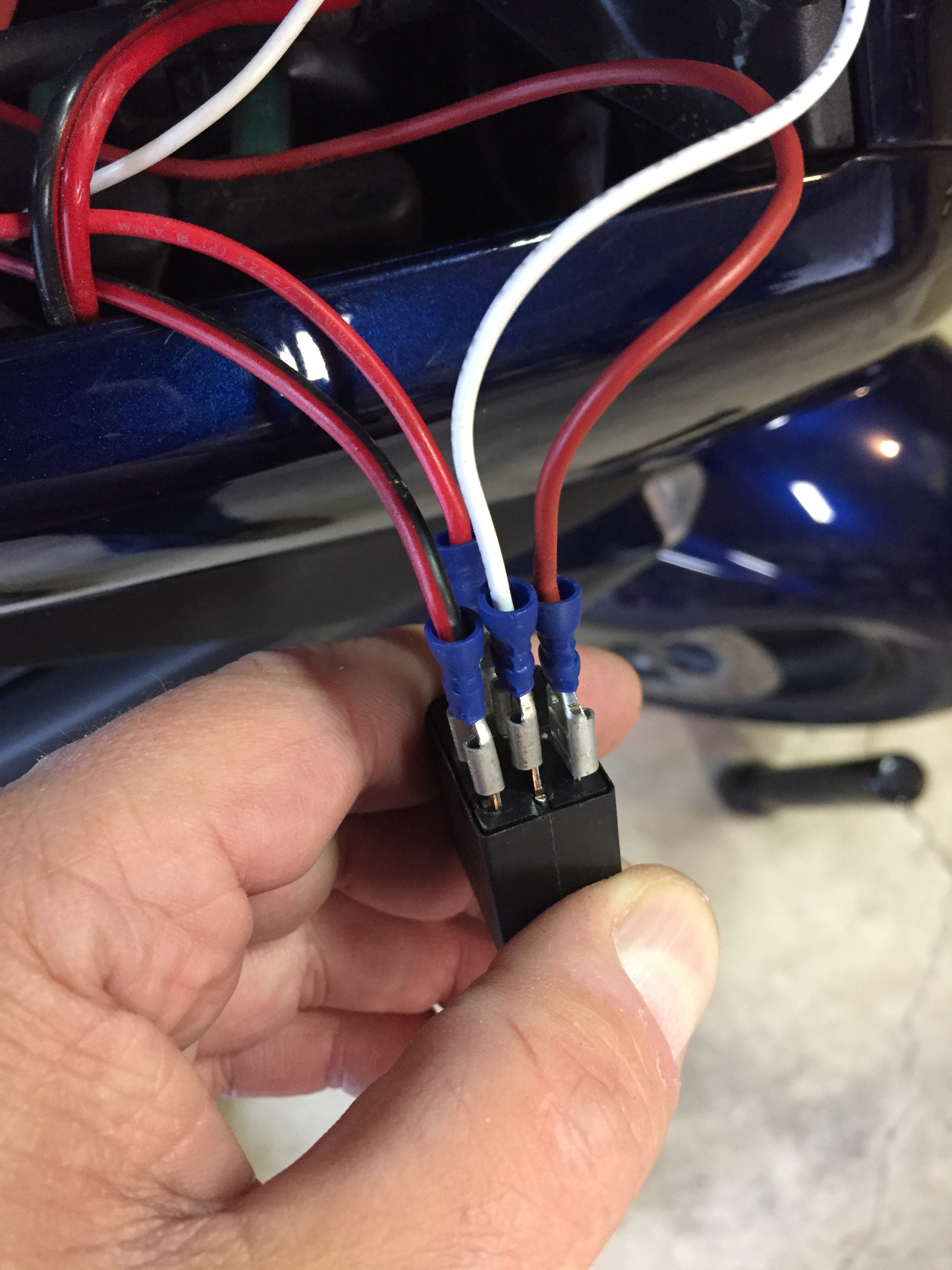 The Bosch change-over relay which the circuit board is replacing. This relay created too much load and caused the high beam indicator on the dash to be lit about 30% on low beam.
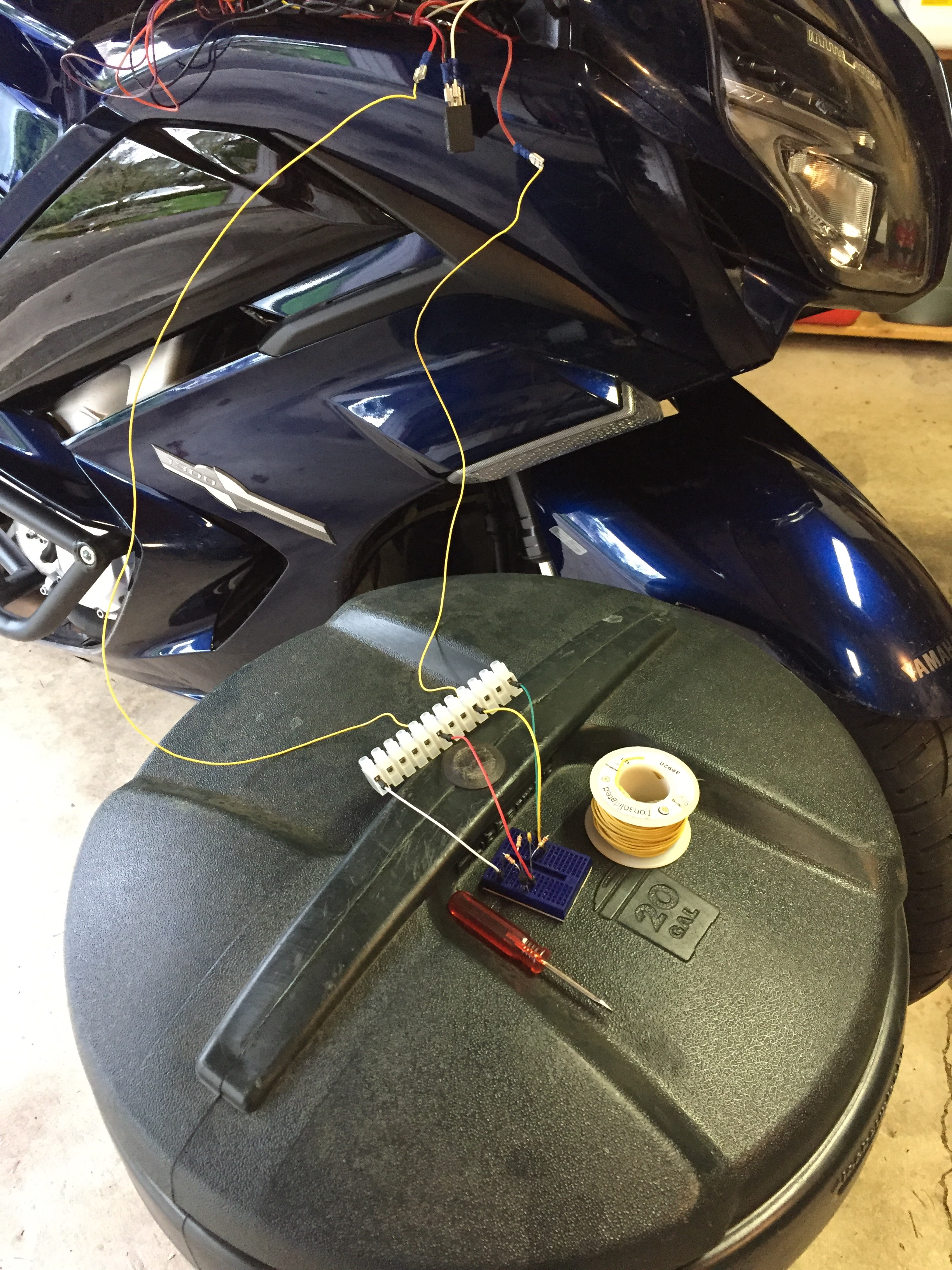 Testing the circuit.
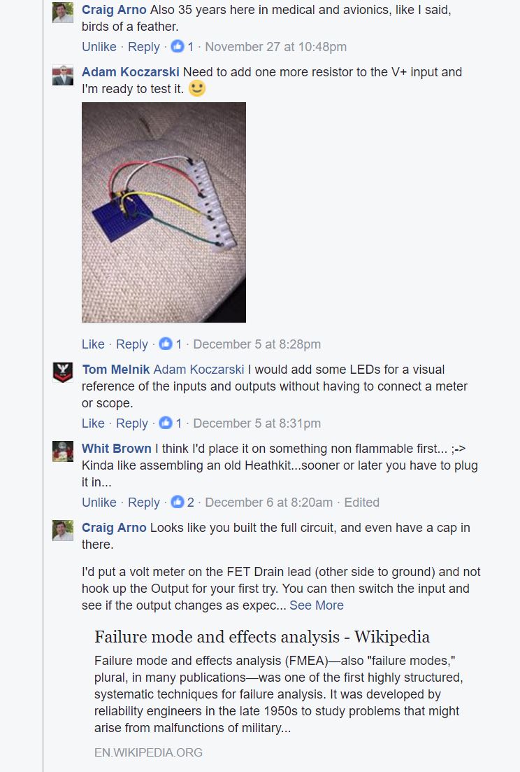
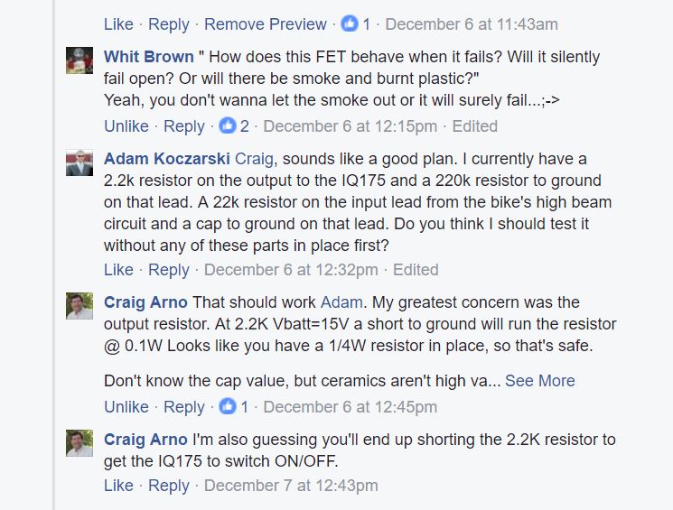
Link to my FaceBook conversation about this circuit here
Return to the 2016 Yamaha FJR1300ES page
——————————————————————————————-
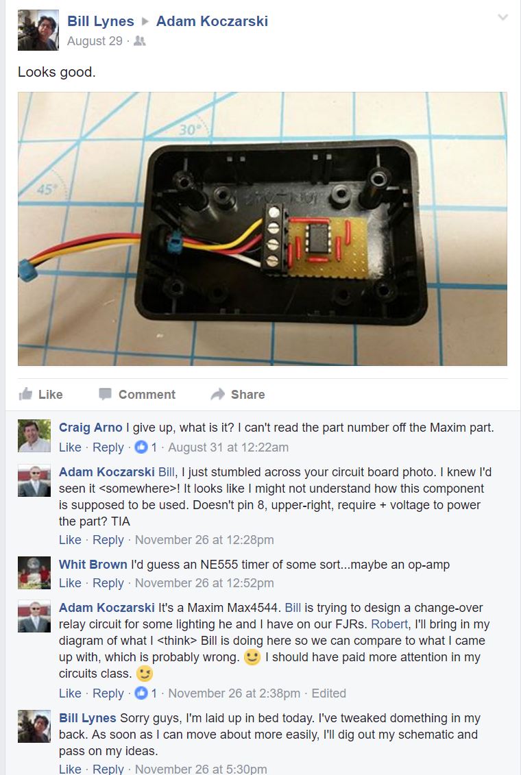
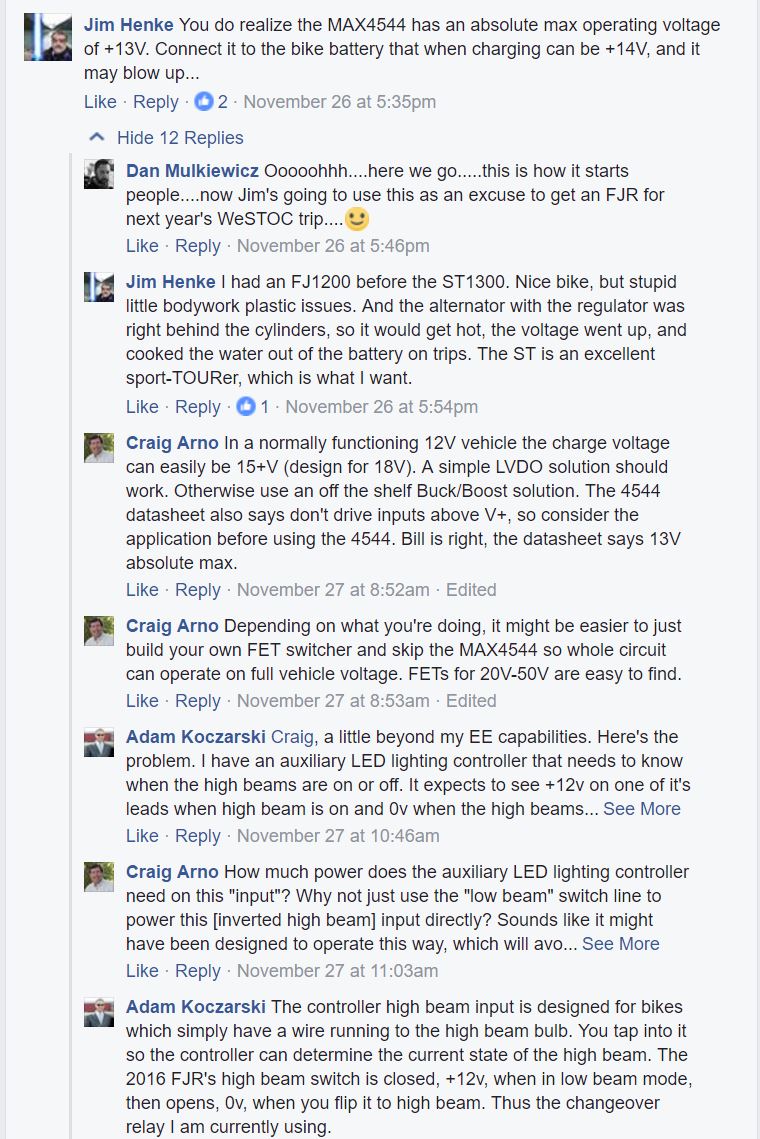
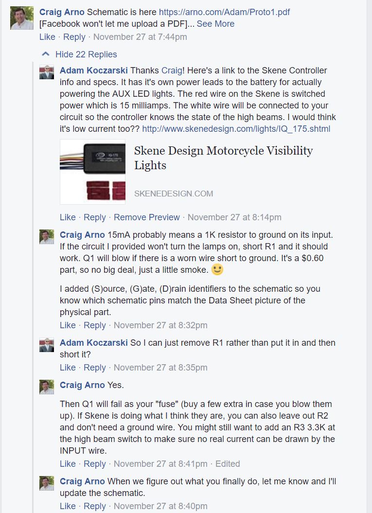
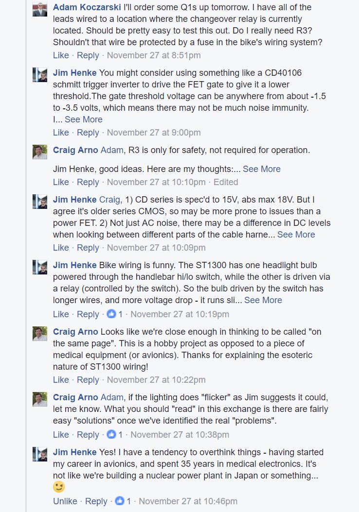
Below are the preliminary designs and a FaceBook conversation with Bill Lynes early on in the design process.
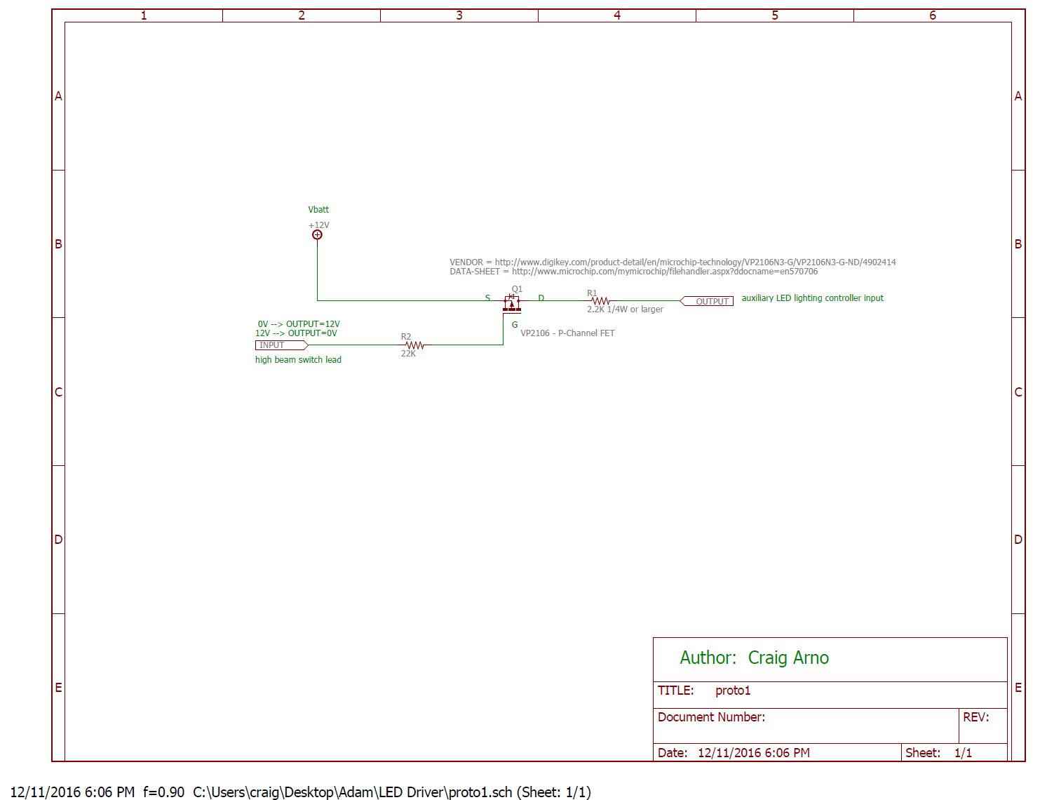 Version 3 – final version.
 Version 2 – Turns out the 22k resistor on the input was required. Without it the LED lights flashed on the low beam setting.
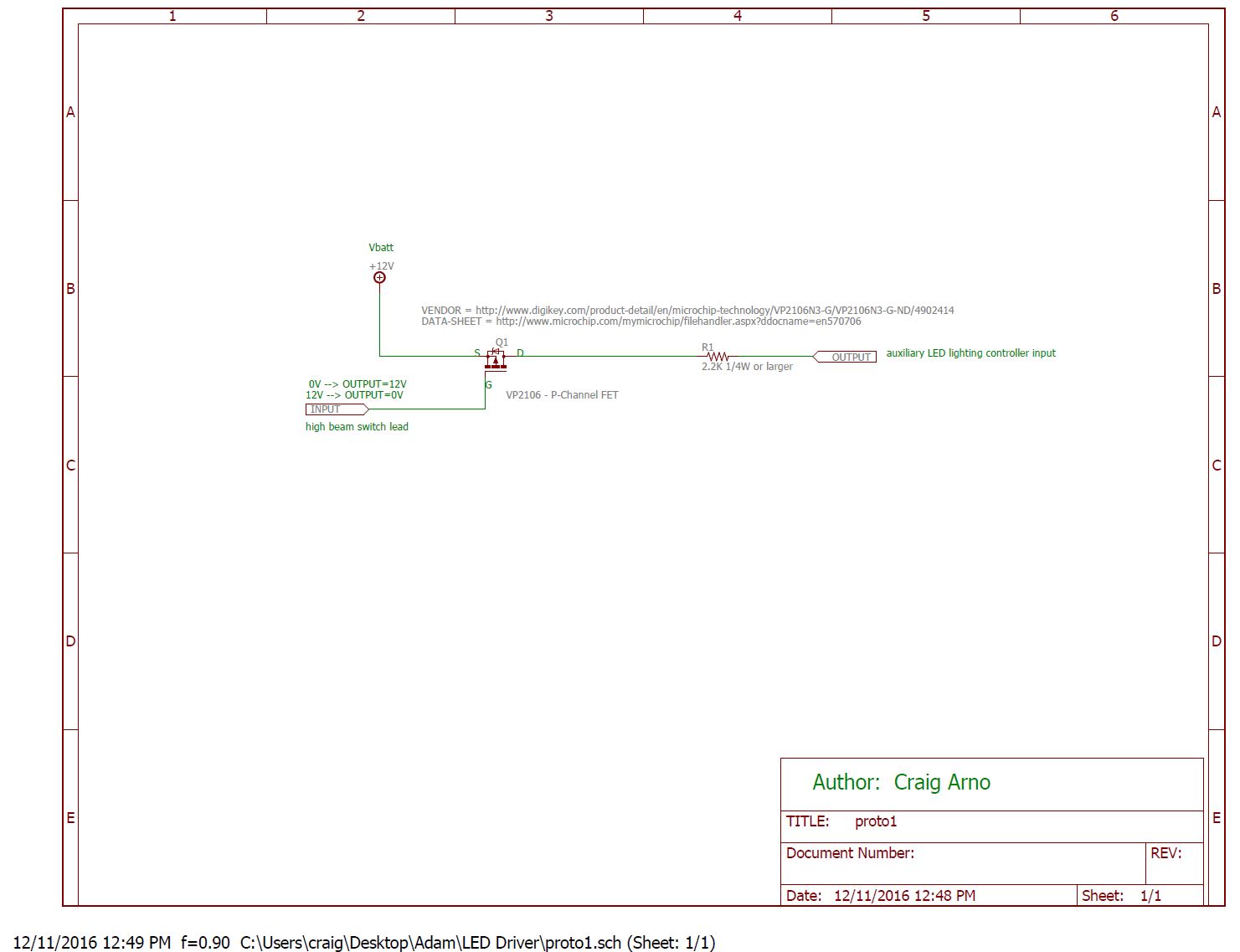
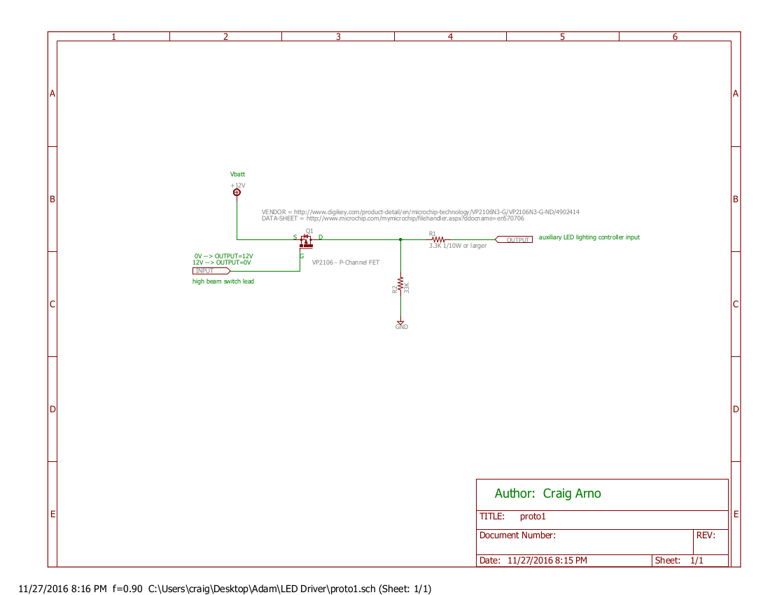 Version 1 – The resistor to ground was not required.
Face Book thread from Bill Lynes page. Wanted to have it here for reference of the beginning of this project Since this all started as his idea.